Bamboo Tips - Contraptions Mills |
|
< Home < Contraptions < Mills
Here are some pictures and/or drawings of Mills from various makers. If the name of the submitter is underlined, you can go to the submitter’s web site.
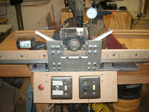
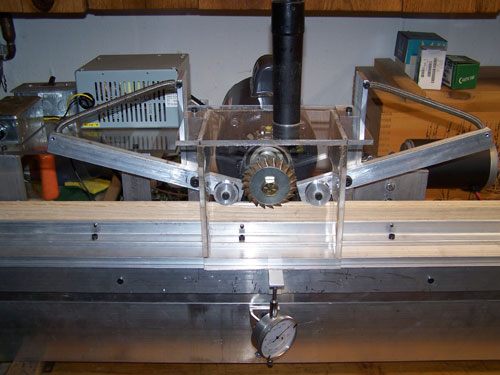
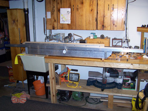
This is an overall front view of the beast. It shows the control panel, dust hood, hold dowmns and carriage.
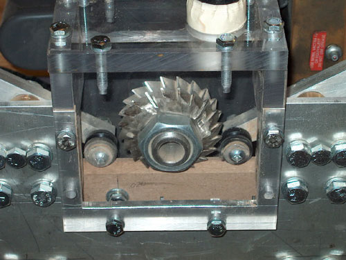
This shows the 1/2" Lexan hood, an old set of cutters, hold downs and part of a taper pattern. The bulk of the mill is made from commonly available 6061 aluminum.
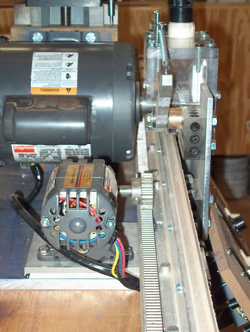
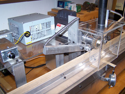
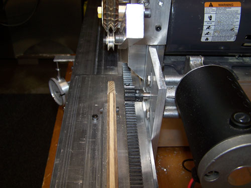
This shows the gear motor, rack and pinion, top of the carriage, motor, hold downs and the back of the dust hood. The dust hood is one piece that can be either removed in parts or as one whole unit. It is rigid as hell although it doesn't look like it. I used 1-2-3 blocks to bolt the hood to the base and to bolt the hold downs. The picture also shows in the upper left-hand corner the RT Gillman dovetail slide that the motor is bolted to. This is a precise, ridged, heavy, very well made slide that I believe sells new for over $1200. It provides a Z-axis so I can raise and lower the cutter head easily. It also locks by tightening the gibbs with a set screw. I picked it up on eBay for less than $200. What a country!
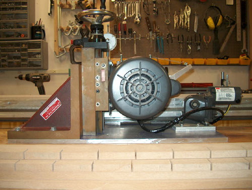
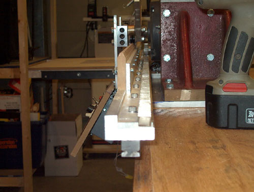
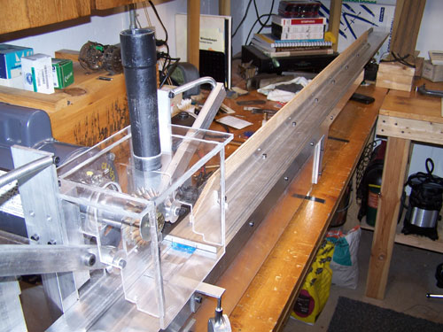
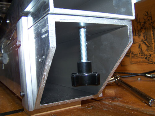
This shows the back of the mill. On the left is the massive 8x8x8 cast iron angle that I picked up for $60 at my local industrial supply house. They had been trying to get rid of it for two years but nobody wanted it because it was solo. This piece was crucial in the machines stability. The surface rust has been removed since these shots and has been hit with camellia oil.
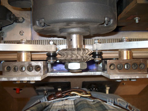
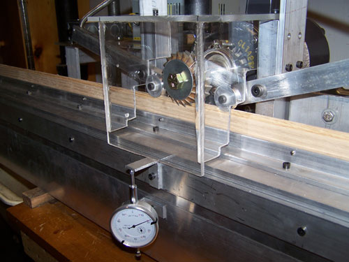
This shows the hold down assemblies, the cutters, the arbor and my belt. I would not advise on the construction of the arbor. It plain old makes me nervous. If I were to change on thing on this I would try to mount the cutters as close to the motor as possible. Alas, there it is. Hope the Lexan works. The hold owns are pretty basic and are as simple as they look. The only thing I can offer are the thrust bearings between each pressure fitting (they look like washers from the top). These enabled me to tighten the arms and hold down wheels to the point where they still move freely but have no side to side slop.
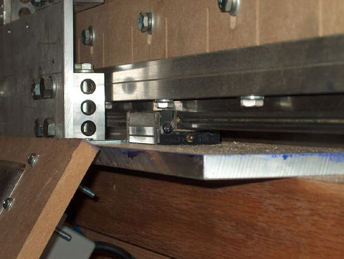
Hear is the heart of the linear motion. The linear rail/bearing block by NSK. These are also known as linear bearings. In the right configuration they can offer precise, ridged and silky smooth motion. These also cost an arm and a leg new, but once again eBay came to the rescue! The carriage in turn is bolted to the top of the rail.
This just gives you a glimpse of the end of the carriage. Hope this helps explain my mess. It works really good out of the gate and I look forward to seeing how close I can get after some tweaking. I'm not a machinist or engineer nor am I an expert on mill building or rodmaking for that matter. I don't aspire to be a mill building/selling professional. I just wanted to make one. I do hope this helps someone out there thinking about building one, whether they learn from it as a bad idea or a good one. Mega kudos go out to Chris Lucker, Dave Leclair, John Channer, Hal Bacon, Bob Maulucci, Jojo Delancier, Bill Taylor and Russ Gooding. Actually, the whole rodmakers community has proven to be the best tool in the box. Thanks gang.
I changed my pattern material to 1/2" phenolic sheet. I also increased the hold down tension. I cut my first pattern tonight (Perfectionist butt with a swell) and the test strip came out, dare I say, good enough to glue up. The flat to flat measurements came out ± .002 and the pattern tolerances came out dead-nuts. The phenolic sheet I got is basically layers of paper soaked in phenolic resins and then heat pressed. It's hard as hell but the paper composition keeps it from being brittle. It's black and dark brown when it's milled on certain angles. I made the pattern on the mill so as to keep the top oriented with the motor arbor. I marked the pattern for 2.5" stations. I chose the shallowest station (ferrule end of the butt section) as zero depth. All of the other stations were milled in reference to this. So, on the perfectionist taper ferrule station 45 is 0, then 42.5 is .0025 deeper than station 0, 40 is .005 deeper than 0, 37.5 is .0075 deeper than zero, etc. The motor mounted on the dovetail slide for a z axis makes this easy. I milled the entire length of the pattern for zero, cranked the motor down .0025 and milled the top to point 42.5 and stopped, reversed it, cranked the motor down to .005, ran it to point 40, etc. For the swell I milled the grip to the proper depth and then ran the pattern under the cutter very slowly over the 2.5" swell and slowly raised it. When all was said and done I lightly filed between stations to smooth things out. The whole process is pretty empirical, but I am assuming that this can provide for pretty unique tapering, one of my sole motivations for building the mill in the first place. Strip prep seems to be of the utmost importance. I plan to make a planer to flatten the enamel side this weekend. I split the initial culm into 1/6's, saw the strips, and then sand my nodes so kinks are no concern for me. Long sweeps seem to be no problem. I am still using the cheap cutters. I really want to see how many rods I can get out of them. At $60 a pair, I can live with 3 rods a side. That's only $10 a rod. I think I waste more glue and varnish than that.
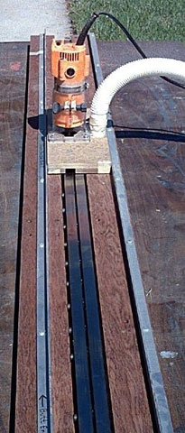
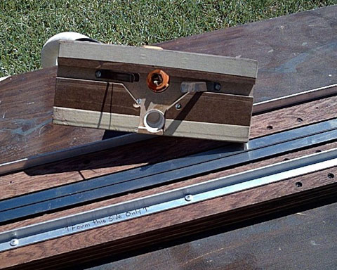
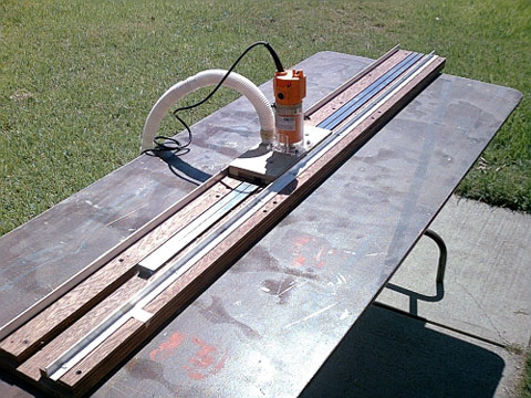
Adam Vigil’s Router Finish Mill
Curt Hugenot’s Hand Mill
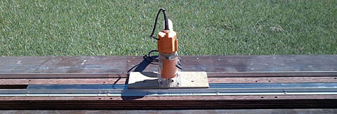
Scott Bahn’s Mill The moveable bed runs with a gear rack powered by a power supply and a 12 volt DC motor. I soldered up a motor controller board that operates the bed with a dial and goes from zero to top speed in either direction depending on which way I turn the dial. Bringing it back to center stops the bed. The milling cutters are run with a Dayton blower motor and are wired to a separate switch. The dial indicator measures relative change and I can raise and lower the base with the threaded knob at one end. I hook up my shop vac at the top of the shroud to suck out the chips and dust. Right now it cuts an untapered strip to a certain size depending on the wooden template I attach to the bed via the aluminum angle. I eventually will experiment with tapered pattern boards but for right now it is acting as a rough beveler only. I can cut a rough finished strip in less than a minute. Beats my old set up or doing it by hand in a roughing form!
|