Building your own wooden planing forms is not difficult but it is time consuming and exacting work. Having the proper tools available is helpful. Some tools you can get by without, and extend the building time, however I don’t see how you can do this project without one of the following: a drill press or a doweling jig. Think about what you are trying to accomplish, building a tool to make tapered bamboo strips accurate to within 001” or less. All of the holes you drill not only have to be in the correct location, they must be parallel to each other otherwise the form will not open or close properly.
Objective: Straight adjustable form that has a “V” groove in each side, top and bottom, with a slope of taper .001”/inch from one end to the other. Close doesn’t count.
Choose the wood: The wood for this project should be a hardwood. Maple is a good choice. Maple drills well, you can tap threads in it, finish it smooth and it is durable. Make sure your selection is straight, no twists and has a straight tight grain. No visible grain at all is better yet.
Start: The first thing you have to decide is the size of your form. The choice is yours. 62” length will allow you to build any two piece rod 10’ or less. If you are never going to build anything over 8’, make a 50” form. If you want to build one-piece rods 8 or less, make a 98” form. It’s up to you. If you are keeping track of these lengths, you will notice that the form is 2” longer than the maximum length of the rod. Reason: The first adjusting station is located 1” from either end of the form.
Let’s build a 62” form where each of the two finished pieces are 1 1/4” X 1 1/4” X 62”. What we are going to do is mill a piece of wood 2 3/4” X 1 1/4” X 72”. Why 2 3/4” wide? Reasons:
After we drill all of the dowel and pull holes we are going to rip it down the middle and the finish off the sawn surfaces back to 1 1/4”. This will also ensure all of our holes line-up by drilling first.
Why 72” length? Later when cutting the groove it’s nice to have the extra length for “run-out” of the cutting tools. When done cutting the groove on both sides, cut off the form to its 62” finished length.
Why a finished form, when closed, 2 1/2” wide? To me it gives you a much more stable surface to work from, especially when using grooved sole planes. With forms that are only 1 1/2” wide it is very easy for the sole of the plane to go over the edge resulting in a planed form. Also makes it easier to get the feel or sense how level you are planing.
Drill the adjusting & dowel holes: Let’s use 1/4” or 5/16” Hex Bolts. Take your pick. Make sure you drill all of the dowel and pull holes, 25 total, with the TAP SIZE DRILL. That’s 12 dowel & 13 pull holes. All holes are midway top to bottom of the form. Pull holes are on 5” centers starting 1” in from what will be the end of the 62” finished form. Dowel holes are on 5” centers mid-way between the adjusting stations. I would suggest when drilling the holes that you use the same form to drill press or doweling jig orientation so that if either does not drill exactly perpendicular at least the holes will be parallel. We will drill the 13 Push holes later after we rip saw and resurface the piece. You may have to tune your drill press table or doweling jig to drill the holes perpendicular to the sides of the form. When you can drill a hole mid-way up the side of a piece of scrap and exit midway on the other side you are ready.
Rip saw and plane the pieces: It’s a good idea to put a pencil mark across one end of the piece before you do the rip cut so you know the orientation of the two pieces later. Rip saw the piece down the middle. You will end up with two pieces 1 1/4” thick, 1 1/4” wide and 72” long. Plane the sawn edges so you end up with two pieces 1 1/4” X 1 1/4” X 72”.
Drill the push holes:
The push holes are only drilled through one side of the form. Midway top to bottom locate the hole 1/2” inboard of the pull holes starting from each end of the form. Which side of the center pull hole should you drill? Take your pick. So now you have 13 push holes drilled. Remember that the drill size is the tap size for the hex bolts you are using. Now tap all 38 holes in this side of the form. Next enlarge all 25 holes in the other part of the form to the shank size, snug fit, of the pull and dowel bolts. After some use the push bolt chew up the rail they are pushing against. This can be over come by drilling a small guide hole smaller than the shank size of a roofing nail and cutting a recess for the head. Insert the roofing nail. Now the push bolt has something solid to push against.
Dowel pins:
I personally don’t think they are needed but if it makes you grin, use them. Cut the hex heads off the 12 dowel bolts. Round the end of the shank. The length of the remaining shank on the bolt should be long enough to protrude slightly through or well into the form when the form is closed. I would suggest threading the same rail that the heads of the pull bolts are located. Some use floating dowel pins, if this is your choice I would point out that when you are drilling holes prior to rip sawing, use a smaller drill than the dowels for their location. Drill out the hole to snug fit size deep enough for the forms to close in each rail later.
Put the form together:
Install the dowels, if you are using them, in their location. Seat the dowels to the start of the shank. For the floating type just put wax on them and put them in the holes. Put some wax or carnuba on the dowel shanks and in the their prospective holes. Put the two pieces together starting the aligning dowels in their snug fit holes.
Put wax on the threads and shanks of the pull bolts and install. Put wax on the push bolt threads and install. You now have a form that can be pulled together or pushed apart. Close the form. The rails should fit together with no gaps and top and bottom aligned flat. If all is well you may not be able to see the joint when the form is closed. If the top and bottom have a slight edge at the joint and you have a planner, no sweat. With the form closed make a very light pass on the top surface and then make another pass on the bottom surface until flat.
The procedure from here on will work for wood or metal forms. Please note that this procedure only requires the setup adjustment once prior to cutting the groove for both sides. Once set, don’t change it. Some may ask, “Why do you have the butt end on the same end of the form on both sides?” It’s so you don’t have to readjust the form from one side to the other to cut the groove.
Cutting the grooves:
One side of the form will be used to make tip sections and the other to make butt sections. The finished slope of the groove on either side will be .001”/inch.
Lay the closed form, with pull bolts facing you, on the bench in front of you. Draw a line across the top of the form directly over each pull adjusting bolt. Label the lines starting on the far-left 0, 1, 2, 3, 4, 5, 6, 7, 8, 9, 10, 11, 12. This will be the TIP side of the form.
Turn the form over front to back. The pull bolts should be facing away from you. Draw a line across the form directly over the pull adjusting bolts as before. Label the lines starting at the left 12, 13, 14, 15, 16, 17, 18, 19, 20, 21, 22, 23, 24.
Objective: Cut a groove on each side of the form so that the slope of the grove is .001”/ inch. so that tip station 12 and butt station 24 will be the butt end of their respective sides.
With the Tip side up, open the form slightly, about 1/16”, its entire length. With a 60° point installed on your Dial Indicator start at tip station 12 and set your Dial Indicator to “0”. Move to station 11 and set the form so the DI reads .005” deeper. Continue towards station "0" setting each station so that the DI reads .005" deeper than the previous.
Recheck your work. When you are done your readings will look like this:
0
1
2
3
4
5
6
7
8
9
10
11
12
.060”
.055”
.050”
.045”
.040”
.035”
.030”
.025”
.020”
.015”
.010”
.005”
0”
Tip - Do Not change the setting of your DI, you will use it later to check your progress of cutting the groove. You also shouldn’t need to change the setup to cut the grooves in the either side.
Example: Tip side station 0 to have a .030” depth with the forms closed. You are finished cutting the grove in the tip side when ALL stations and every thing in between reads .090” with the above setup. You are finished cutting the groove in the butt side when ALL stations and everything in between when the DI reads .150” The resulting grooves will have slopes of .001”/inch.
Results: Closed form groove depth dimensions of the finished form:
Tip side
0
1
2
3
4
5
6
7
8
9
10
11
12
.030”
.035”
.040”
.045”
.050”
.055”
.060”
.065”
.070”
.075”
.080”
.085”
.090”
Butt side
12
13
14
15
16
17
18
19
20
21
22
23
24
.090”
.095”
.100”
.105”
.110”
.115”
.120”
.125”
.130”
.135”
.140”
.145”
.150”
Getting ready to cut the 60° groove:
You will need to make a couple of cutting tools. Here are two: “60° Lathe Bit Plane”, for fast cutting and the “File Plane”, for final cutting. The FP is featured along with how to use it in “Power Fibers” October 2001 issue.
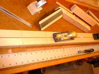
60° Lathe Bit Plane:
You can see the lathe bit plane at the top of this photo.
Objective: Mount a 3/8” 60° lathe bit in a self-centering plane type hardwood block. The bit must be adjustable up and down. You will find out that very small cuts are best. You can push it or pull it but you must keep the bit centered in the gap of the form.
Using Maple stock:
Mill 2 piece 3/4” X 1” X 12” (stock for sides of tool)
Mill 1 piece 3/8” X 1” X 12” (spacer stock)
Mill 1 piece 3/8” X 3/8” X 12” (guide stock)
Cut: 2 pieces 4” long from spacer stock. Cut remaining in half.
Cut a 60° V bevel point on each end of the 3/8” X 3/8” guide stock, then cut in half.
Lay one of the side pieces on a flat surface.
Using the lathe bit and the two 3/8” X 3/8” as spacers place the lathe bit in the center with a 4” piece on either side followed by a V block on either side followed by one of the 2 scrap pieces. Glue the pieces without gluing the bit and V blocks. Glue the remaining side in place.
When everything is dry trim the ends of the scrap pieces flush. You should now have a block approximately 1” high 12” long and 1 7/8” wide with three 3/8” square holes. At the center hole, drill and tap a 1/4-20 hole for a setscrew to hold the bit adjustment.
The forward and trailing V guide blocks are needed to keep the bit centered in the gap. They must also be able to move up and down freely to follow the width of the gap. Drill a ¼” dowel hole at a location where the V block’s downward travel can not project more than 3/8” below the bottom surface of the plane. Glue a dowel leaving a projection out each side. Mount a flat spring pushing down on the dowel.
You may want to mount a handle like a block plane or a ½” dowel projecting to either side or simply round and sand the trailing edge of the plane. Just rounding works fine.
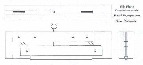
File Plane:
The File Plane works on the principle of a parallelogram. The cutting tool is a three-corner file. Epoxy the file to one side of the parallelogram later. Mid way on the opposite side drill and tap a 1/4-20 hole. Now, with a 1/4-20 thumb bolt you can force the parallelogram apart.
The short sides of the parallelogram are made from steel strap with 1/4 inch holes on about 1 1/8” centers.
The long sides are slightly thicker than the flat width dimension of the file. The length will depend on the file you wish to use, probably about 6” or 7”. Mill a piece about 24” long, you will use the scrap latter. The width will be about 5/8”. Drill a 1/4” hole 1/2” from the ends. Cut a slot, thickness of strap material, in each end of the long sides. Using 1/4” steel dowel pins, length equal to thickness of long sides thickness, put the parallelogram together. The slots are cut deep enough so the long sides will come together. Now you can center and epoxy the file in place.
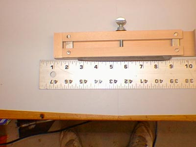
Build a box, open top and bottom, to hold the parallelogram. The inside width will be the same as the thickness of the long sides of the parallelogram. The inside length will be the length of the parallelogram when the long sides are touching. The height will be slightly less than the total height of the parallelogram when fully extended, not including the file.
Mill two 1/2” thick pieces of stock for the sides of the box. Cut two pieces from the left over scrap from the long side of the parallelogram to a length equal to the height of the box. These are the ends of the box. Glue one piece aligned to the right hand edge of the side piece. Using the parallelogram as a guide with the long sides touching, position and glue the second end piece.
Take the parallelogram apart. Glue the top piece, the one with the bolt hole, aligned with the top edge of the box and butted against the left end piece. Please note: The cutting direction of the file will be pointing to the left when assembled.
Sand both sides of the piece that has the file epoxied slightly. We want this piece to be able to move up and down in the box, not a jam fit. Put the parallelogram back together with the file’s cutting grain pointing to the left.
Glue the other side in place, add some 1/4” dowels for strength if you wish, trim off the ends, relieve the edges and sand. Round over the trailing top end for palm comfort.
Cutting the groove:
Secure the previously setup form, butt end tip side up to the left for right handers, to the bench top. This is where the extra length of the form will be used as runout to help keep the 60° LBP centered.
Using the 60° LBP set the lathe bit to just touch the gap on the butt end of the form. You will quickly find out that you can not be too aggressive in the amount of material you try to remove per pass. You want to shave it, not hog it out. When the tool will no longer cut adjust the bit down and shave some more. Continue this process until the lathe bit is making contact with the form the entire length of the gap. When you get to .004 - .005 of the final depth of the groove switch to the FP. You will find the FP will load up rapidly when filing wood, not so with metal. Clean often and take your time. This is not the time to screw-up. When you get to the depth dimensions as stated above at all locations along the groove, you’re done with this side.
Turn the form over and do the other side. After the grooves are finished on both sides, trim off extra length to final form length dimensions.